|
|
|||||||||
| ► Processes of Joining Materials Copyright © 2001 Thomas W. Eagar | |||||||||
| ◄home | |||||||||
|
1. Overwiev 2. Fastening 3. Bonding Process Fundamentals 4. Welding Using Interfacial Shear 5. Adhesive Bonding 6. Diffusion Bonding 7. Soldering and Brazing 8. Fusion Welding 9. Joint Preparation and Weld Defects 10. Conclusion
OVERWIEV Joining is literally where all the parts of the manufacturing process come together. As such these processes are essential to virtually every manufactured product. Nonetheless, these processes often appear to consume greater fractions of the product cost and create more of the production difficulties than might rightfully be expected. There are a number of reasons for this. First, welding and joining are multifaceted, both in the variations of the process (fastening, adhesive bonding, soldering, brazing, arc welding, diffusion bonding, resistance welding, etc.) and in the disciplines which must be brought to bear to solve a problem (mechanics, materials science, physics, chemistry, electronics, etc.). It requires an engineer with unusually broad and deep training to bring so many disciplines together and to apply them in depth to such a variety of processes. Second, when welding or joining difficulties arise, it usually happens well into the manufacturing stream, where the relative value of scrapped parts is high. A final reason why welding and joining processes are important to manufacturing is that a very large percentage of product failures occur at joints. Joints are often the weakest part of the assembly and usually are located at the most highly stressed points. Careful attention to the joining processes can produce great rewards in manufacturing economy and product reliability. We will discuss fastening as well as the true bonding processes, which include adhesives, soldering, brazing and welding. The emphasis will be on the fundamental aspects of each process rather than the specific details. There are very many joining processes. One of the greatest difficulties for the manufacturing engineer is to determine which still produce acceptable properties at the lowest cost. There are no simple answers. A change in the part geometry, or the material, or the value of the end product, or the size of the production run, or the availability of joining equipment can influence the choice of joining method. On small lots of complex parts fastening is often the best choice; while for long production runs, welds would often be stronger and less expensive. The perfect joint is indistinguishable from the material surrounding it. Some processes, such as diffusion bonding, come very close to this ideal; however, these processes are either expensive or restricted to few materials. There is no universal process that will perform adequately on all materials in all geometries. Nevertheless, virtually any material can be joined in some way, if one is willing to pay the price; although joint properties equal to the bulk material cannot always be achieved. Our ability to join a material economically often places a limitation on the usefulness of the material. Aluminum is used extensively in aircraft and is joined by adhesives, fasteners and welding; yet none of these processes has proven economical enough for aluminum to replace steel in the frames of automobiles. The rise of composites in aircraft is limited in large part by an inability to achieve adequate strength in the joints. It is essential that the manufacturing engineer work with the designer from the conception of a product, so that compatible materials, processes and properties are selected for the final assembly. Too often a designer leaves the problem of joining the parts to the manufacturing engineer, with resultant escalations in costs and decreases in reliability. If the design has been planned carefully and the parts have been produced accurately, the joining process becomes much easier and cheaper, and the quality and reliability of the product are enhanced.
Fasteners come in a myriad of shapes, sizes and forms; including screws, nails, rivets, stitches, staples and the like. Press fits, shrink fits, rolled seams and lock seams are methods of fastening which do not use separate fasteners, but rather are designed into the parts to be joined. One author has estimated that over two million different fasteners are in use. There are three main advantages of fasteners over most other joining processes. First, virtually any shape or material can be joined. Second, the joints are usually temporary or only semi -permanent; hence the product can be disassembled. Third, fastening is often the least expensive method for low volume production. This is mainly because the properties of the fastened joint are generally known or calculable; there is no need to develop special procedures or to perform qualification tests on fasteners. Anyone of these three advantages can be an overriding factor in determining the use of fasteners in manufacturing. There are also disadvantages to using fasteners as compared with true bonding processes. Fasteners often do not develop the full strength of the base materials, particularly if the base material is a metal In addition, fasteners do not produce hermetic seals. The fastener itself is an extra part to be manufactured; plus making the hole in which it is inserted adds another operation. Insertion of fasteners is not readily automated unless the fastening method is designed for this purpose. Inserting a screw into a hole is a simple task for a human but is very difficult for a robot. Finally, fasteners can create additional concerns, such as loosening from vibration or corrosion. Nonetheless, each of these disadvantages noted, except strength and cost, generally can be overcome by combining fastening with another process. For example, lock seams in steel water pails have adequate strength and the zinc galvanizing provides the seal. Adhesives prevent loosening of screws and use of more corrosion-resistant fastening materials than the base material prevents rapid deterioration of the fasteners. Unfortunately, combining fastening with solders or adhesives or using more noble fastener materials tends to increase cost. As a result, fasteners should be used only when one of the advantages outlined in the preceding paragraph overrides benefits of one of the other joining processes.
Apart from fasteners, each of the other joining processes involves formation of a bond between the parts. These processes include adhesives, solders, brazes and welds. Generally, any two solids will bond if the surfaces are brought into intimate contact. Unfortunately, there are two factors inhibiting this contact. The first is surface contamination. Any freshly produced surface exposed to the atmosphere will adsorb oxygen, water vapor, carbon dioxide and hydrocarbons very rapidly. Assuming that each molecule that hits the surface will be adsorbed, the time-pressure product to produce a monolayer of contamination is 108 atm-seconds. For example, at 10-5 atm pressure, the contamination time is one millisecond, and at one atmosphere it is only 10 nanoseconds. The second reason why two surfaces will not bond when placed in contact is that the solid surfaces do not mate perfectly. On an atomic scale, the smoothest surface contains numerous peaks and valleys; hence, the true contact area is usually less than 10% and rarely more than 30% of the apparent contact area. This has been confirmed by tests in ultrahigh vacuum and in space. At such low pressures, the surface contamination time increases to minutes or hours. Two freshly cleaned surfaces placed in contact in such an environment will bond with approximately ten per cent of the bulk material strength. In this sense, the principles of bonding are the opposite of the principles of lubrication. In bonding, contamination must be prevented; in lubrication, the proper type of contamination is added to the surface to prevent bonding. The contamination and the partial contact area can be considered as chemical and geometric barriers to bonding, respectively. Any successful bonding process must overcome both of these problems.
If two materials, usually metals or plastics, are placed in contact and the interface is sheared in a manner, which disrupts the surface contamination while also mechanically excluding the atmosphere, a bond will be formed. This is important in joining of wires to integrated circuits or sealing metal cans around such circuits. The interfacial shear is essential, as experience shows that merely pressing two surfaces together without sliding between the surfaces will not produce a bond. Cone-shaped or beveled punches are often used to produce adequate interfacial shear. Studies have also shown that metals with a high oxide hardness to metal hardness ratio are easiest to cold bond; In practice, this means that pure aluminum is the easiest material to bond, followed by tin. In fact, steel cans for encasing semiconductors are often tin-plated to improve cold bonding. Ultrasonic welding, in which a 10 kHz to 75 kHz vibration is imposed on two parts placed in contact, is another form of cold welding. The vibrations create microscopic shear, which generates new uncontaminated surface area without macroscopic deformation of the part; however, it must be remembered that the contamination is merely redistributed and is not displaced from the joint. As a result this rarely produces more than fifty percent actual bond area. The key to cold welding is production of significant interfacial sliding. In most cases, the ability to generate such shear is strongly dependent on the part geometry. If cold bonding is practical, it is often quite economical, especially in high volume production, as no filler material is needed and the process is rapid. In addition, the absence of heat reduces distortion of the overall part and simplifies tooling and automation. Yet another process, which uses interfacial shear, is friction welding. In thermoplastic materials, which have low heat diffusivity, sliding of the interface can generate enough heat to soften or even melt a thin zone. The contamination is displaced, hence, producing intimate contact of the polymer with a resultant bond. In metals, with much higher heat diffusivities and melting temperatures, much more sliding is necessary to soften the metal. Typically, circular parts rotating at hundreds of rpm with respect to one another are pressed together under high axial pressure. With steel or other high melting alloys, the interface rapidly becomes red hot and begins to deform. The rapid shear and the mechanical exclusion of the atmosphere produce intimate metal contact. If all of the contamination is removed from the interface by extruding hot metal out of the weld zone, a full strength, nearly perfect weld can be formed.
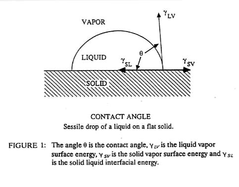
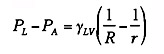
Adhesives consist of fluids (many of them very viscous) that fill the hills and valleys of the solid surfaces. The adhesive bond is created by surface tension forces or mechanical interlocking of the adhesive in the pores and valleys of the solid. This produces bonds that are weaker than the interatomic bonds formed during welding. As a result, adhesives work best when joining materials of high surface to volume ratio such as sheets, fibers or small particles. The large joint surface area provides strength and distributes the forces over a large area, thus reducing stress concentrations in the assembly. The adhesive can also serve as an electrical insulator or a hermetic seal in some applications. Virtually any combination of materials can be joined rapidly in a manner that is easy to automate. The cost can vary greatly from much less than a dollar a pound for common adhesives to hundreds of dollars per pound for the most exotic ones. Adhesive bonding is unusual among the bonding processes in that all of the chemical contamination of the surface need not be removed. Indeed, some surfaces, such as chromated aluminum or phosphated steel, are purposely "contaminated" with porous surface films that enhance the bonding of the adhesive. The most critical property of an adhesive is the surface energy, (equivalent to surface tension) which determines the wetting angle between the fluid adhesive and the solid adherend (see Figure 1). A low angle represents good wetting and a high angle represents poor wetting. Generally, contact angles of less than 30° are necessary for bonding.
Many factors influence this wetting angle, including surface roughness of the solid (better wetting) and surface contamination (poorer wetting). The wetting angle also can exhibit hysteresis, as the angle is often less when the liquid first flows onto the surface. As the fluid recedes, some adhesive is trapped on the surface of the solid and the wetting angle increases, sometimes producing a weaker bond upon reapplication of the adhesive.
If r < R, then PL - PA is
negative and the pressure in the air is greater than the pressure in the
liquid. The two solids are held together with a pressure, PA -
PL. Thus, any thin film of fluid, which wets two solids, will
act as an adhesive. It is seen from Equation 1 that the thinner the film,
the greater the adhesion; however, formation of very thin layers requires
very low viscosity fluids. Such thin fluid films can produce high tensile
strengths but are relatively weak in shear. An example is Johansson blocks
that are "wrung" together. These steel blocks are used as measurement
standards by machinists and have exceptionally flat and smooth surfaces. If
two blocks are slid or wrung together carefully, it is found that they will
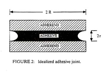
bond with surprising strength. It has been shown that the adsorbed water
vapor combined with the flat smooth surface, produces a joint such as shown
in Figure 2 with water as the adhesive.
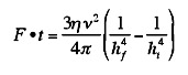
where eta is the viscosity of the adhesive, nu is the
volume of the drop, hi is the initial plate separation and
hf is the final plate separation. If the plates are
circular disks of radius a,
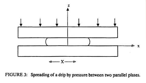
This is known as the Stefan equation and was derived from the viscous flow resistance for squeezing a non-wetting liquid between two circular plates, but it is also valid for the force of separation of two plates with a wetting liquid of initial thickness hf. One can readily see that if hf is small enough, even low viscosity fluids such as water can have an adhesive effect. Equation 3 also shows that the time to squeeze a joint together increases directly as the viscosity of the adhesive increases. For a bonding pressure of one atmosphere a viscosity of 1 g/cm/sec, a disc of one centimeter radius, and final joint thickness of 0.01 cm, the bonding time is 0.02 sec. If the disc radius is ten times larger, the bonding time increases to 200 seconds. Clearly, for large bonding areas, a low viscosity adhesive is desirable to form the joint, but a high viscosity adhesive is needed to achieve strength. These conflicting requirements suggest a need for an adhesive that is applied at low viscosity but hardens to high viscosity. There are a number of ways this can be achieved. 1. Cooling of a thermoplastic material. Hot-melt adhesives flow easily at high temperatures but harden on cooling, thus increasing the bond strength. The asphalt used to pave roads is a hot melt adhesive. 2. Release of a solvent or carrier. Porous paper absorbs the moisture from many types of glue, allowing them to harden. Other adhesives contain volatile solvents. Any such adhesive must be used with porous adherends so that the solvent can escape. Water-based glues are ineffective on metals and many plastics for this reason. 3. Polymerization in situ. Epoxies polymerize by mixing two components together. Cyanoacrylates are polymerized by the moisture, which is adsorbed on most surfaces, while anaerobic adhesives polymerize when they are deprived of oxygen in the air. For this reason anaerobics are often used to bond fasteners to prevent them from loosening. In addition to these methods of increasing the viscosity after the adhesive is in place, there are many pressure-sensitive adhesives, which do not increase in strength upon application. As a result, these pressure-sensitive adhesives are easy to remove. A common example is masking tape. The release strength of such an adhesive is very nearly the same as the force-time product used to apply the adhesive. Referring again to Equation 3, a high force applied for a long time should produce a thin joint of high strength. The joint strength will also follow Equation 3.
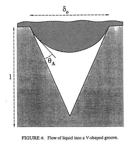
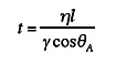
There is another adhesive bonding mechanism in addition to that described by Figure 3 and Equation 1. This second method consists of adhesive fluid infiltrating pores on the adherend surface as shown in Figure 4. The time required for the fluid to fill a pore to depth, l, is given approximately by
It can be seen that a low wetting angle and a high interfacial tension will reduce the time to fill the pore. "Tacky" adhesives fill pores quickly. Once the pores are filled, mechanical interlocking occurs. Aluminum that has been chromated or steel that has been phosphated will often produce very strong adhesive bonds because the chromate and phosphate coatings are very porous and hence mechanically interlock with many adhesives. The choice of a rough or a smooth adherend surface depends on whether surface tension forces (Equation 1) or mechanical interlocking provides most of the adhesive strength. If surface tension forces predominate, a rough surface may produce a larger effective joint thickness and hence lower strength. If mechanical interlocking predominates, increased roughness may be beneficial. Lap joints loaded in shear generally produce the strongest adhesive bonds. The deformation of the adhesive distributes the load over a large area, thus reducing concentrations of stress. Lap joints loaded in tension, that is, a peel test, are among the weakest joints since the stress is concentrated at the leading edge of the adhesive. Finally, one must remember to consider the long-term performance of adhesives. Since this bonding method does not create strong chemical bonds, there are greater possibilities for joint degradation in service. For example: adhesive bonding of aluminum is very effective in aircraft; however, the costs of these adhesives are often high because they must be extremely moisture-resistant. Less expensive adhesives, as often used in automotive applications, can allow moisture to infiltrate the joint over time causing formation of aluminum hydroxides that weaken the joint. If the proper adhesive / adherend combination is not chosen, a strong initial bond can deteriorate in service.
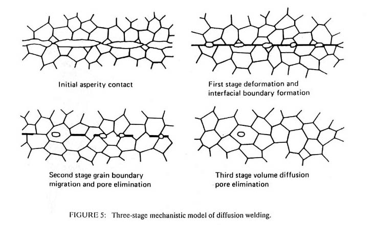
If some metals or ceramics are held together under high pressure at elevated temperatures for extended periods of time they will bond. The addition of heat permits deformation of the microscopic points of contact between the two materials, thus greatly increasing the true area of contact. If the surface contaminants are soluble in the base material, the contamination will diffuse away into the bulk, permitting true interatomic bonding at the interface. Thus metals such as silver, the oxide of which is not stable at high temperatures, are very easy to bond by diffusion. Iron, titanium and copper, although capable of forming stable oxides, are also easily bonded because the oxide will diffuse into the base metal at the elevated bonding temperatures. Aluminum and magnesium are difficult to bond by this method because their oxides are stable and are not readily soluble in the bulk metal. The primary variables controlling diffusion bonding are pressure, temperature, surface finish and surface cleanliness. Typical contact pressures are 500 to 5,000 psi at temperatures of six-tenths or more of the absolute melting temperature of the metal. Contact times can be as short as a few minutes but are commonly an hour or even tens of hours. As a result, diffusion bonding is generally an expensive process. Nonetheless, it can produce nearly ideal joints, which are indistinguishable from the base metal. Many complex, inaccessible joints can be formed without distortion of the part or use of filler material thus providing great precision in the assembly. A disadvantage is that the high temperatures usually will remove any strength in the base metal due to cold work or lower temperature heat treatment; thus subsequent heat treatment may be required. Diffusion bonding can be used to join many dissimilar materials that would otherwise be incompatible. The major problem with such dissimilar joints is the formation of residual stresses at the interface during cooling due to thermal expansion differences between the materials. Interlayer materials with intermediate expansion rates are sometimes used to reduce these stresses. Another potential problem is formation of brittle intermetallic compounds with some material combinations. Again, interlayer materials can often be used to alleviate these problems. Diffusion bonding is often divided into three stages as shown in Figure 5. In stage one, the true contact area is small. Application of pressure and heat causes the asperities to deform and grow, until a bond plane containing a large number of porosities is formed. At this point, stage two begins and further application of pressure is not necessary. Continued heating causes the porosities to shrink in size. Eventually, as the bond becomes more complete, metal crystals grow across the bond interface, trapping the porosity in the center of a crystal. This is the beginning of stage three and is essentially the end of the bonding cycle; for no matter how long one heats the materials, it is extremely difficult to eliminate these last porosities. Nonetheless, if the proper bonding temperatures and pressures are chosen for stages one and two, a nearly perfect bond will be formed by the time stage three occurs.
An important variation of diffusion bonding is transient liquid phase (TLP) bonding. This has been used since ancient times, although in recent years it has been patented, primarily for aerospace applications. In TLP bonding, a liquid is introduced between the two solids. This liquid fills the voids, thus providing nearly complete contact. This accelerates diffusion across the interface. As a result, TLP bonding is often much faster than diffusion bonding, requiring a few minutes to a few hours depending on the thinness of the liquid film. Since the liquid fills the joint without application of pressure, contact pressures of less than 10 psi are required, essentially only for holding the parts in alignment. This greatly simplifies tooling. The transient phase in TLP bonding is the liquid. The liquid must be a low melting alloy in which one or more elements will diffuse rapidly into the base metal. As this component diffuses away, the interfacial region becomes enriched in the non-diffusing elements, which solidify due to loss into the bulk of the diffusing component. This is termed isothermal solidification, as the liquid freezes at constant temperature due to a compositional change rather than the more usual athermal solidification, which occurs at constant composition as the temperature is reduced. The patented process includes nickel-boron liquids in which the boron diffuses away leaving a higher melting nickel alloy at the interface, but the process occurs in other systems as well. For example, eutectic lead-tin soldered to copper will melt at 183°C, but during holding for ten hours at 200°C, the tin reacts with the copper, leaving a lead-enriched solid zone which maintains strength to 300°C even though the joint started as a liquid at 200°C. The major problem with TLP bonding is that it is not applicable to all materials. There are a number of metallurgical restrictions such as a low melting alloy, one component of which is soluble in the base metal, diffuses rapidly, is not harmful to mechanical properties of the base metal and does not promote formation of brittle intermetallic compounds at the interface. In addition, the bonding times are still relatively long, thus requiring use with high value added parts. Nonetheless, when TLP bonding is possible, it generally produces joints of excellent strength and high reliability. Yet another variation of diffusion welding is activated diffusion bonding. In this process, the surface to be bonded is coated with another element, which promotes rapid diffusion and decomposition of the surface contaminant. The most common activated layer is silver, which readily dissolves many metal oxides and is soft enough to promote large areas of interfacial contact. For example, steels can be diffusion bonded at temperatures as low as 200°C when a silver layer is introduced. No liquid phase is present and the silver remains as a thin layer in the final joint. In the absence of silver, the iron oxides would not decompose at such low temperatures, but with the silver, very strong bonds can be formed.
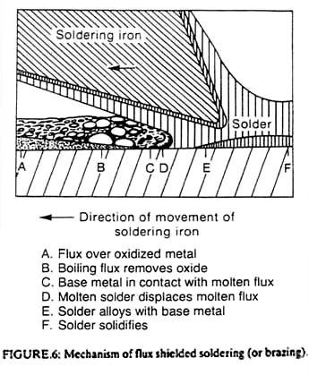
Soldering and brazing are identical processes differentiated only by the temperature at which they occur. Soldering is performed below 425°C while brazing is the same process performed above this temperature. The basic process is shown in Figure 6. A heat source, in this case a soldering iron, heats the base metal, a flux and the solder. The flux dissolves the surface contamination, alloying the liquid solder to contact the base metal directly. The solder must wet the metal and must have a sufficiently large surface tension to displace the molten flux, which must have a low surface tension. Molten metals have very high surface tensions, while organic compounds and inorganic salts have lower surface tensions; hence, the solders are usually metals while the fluxes are organic or inorganic compounds. The base material can be either a metal or a ceramic. Indeed, brazing is one of the most useful methods for joining ceramics or glasses to other materia1s, particularly when the joint must operate at elevated temperatures.
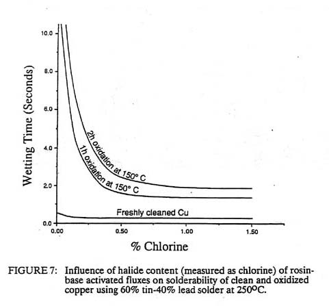
Although rough surfaces are generally detrimental to most bonding processes, roughness usually enhances the wetting of the solder to the base metal. Increased bonding temperatures generally enhance the flux cleaning of the surface and increase the speed of bonding. Both soldering and brazing are readily automated and can often be accomplished at very high speeds. Selection of the proper flux and maintenance of surface cleanliness are essential to soldering and brazing. If the flux is not reactive enough, it will not decompose the surface oxides. For example, rosin fluxes for lead-tin solders are only weakly reactive with copper oxide. If the copper surface has been freshly cleaned, the rosin will promote wetting within less than a second as shown in Figure 7. After one hour an invisible copper oxide film forms on the copper, which inhibits the wetting. Addition of even small amounts of chloride ions will aid in decomposition of this oxide film, greatly reducing the wetting time. Addition of the chlorine to the rosin produces an 'activated" flux which generally provides more consistent soldering but which could lead to long term corrosion problems if not completely washed from the joint.
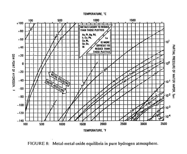
Some materials, such as titanium or beryllium have such stable oxides that no soldering flux has been developed. Aluminum solder fluxes have been produced but often create problems, as their reactivity is marginal. Due to the higher temperatures used in brazing, more aggressive fluxes are possible and virtually all metals and ceramics are brazeable even if some are not solderable. Often brazing is carried out with a reactive gas such as hydrogen or in a vacuum, rather than with a flux. Figure 8 shows the relative stability of various metal oxides as a function of temperature, hydrogen dew point and partial pressure of water vapor. The metals whose oxides decompose at the lower temperatures are the easiest to braze or solder.
The strength of a solder joint is controlled primarily by the creep strength of the solder. This is, in turn, controlled by the melting temperature of the solder. A general rule suggests that solder joint stresses should not exceed 1,000 psi above 0.75 of the absolute melting temperature. This same limitation also applies to braze joints although braze joints at room temperature are usually well below this creep limit, and strengths of 5,000 to 10,000 psi are easily attainable in most brazes at room temperature. The actual strength can be much higher depending on the joint thickness as shown in Figure 9. As the joint becomes thinner, the braze metal is constrained from deforming due to the adjacent base metal. This produces a triaxial state of stress in the braze, which makes the entire joint stronger. This phenomenon is termed contact strengthening. In theory, contact strengthening will continue to increase as the joint becomes thinner. For example, thin silver activated diffusion bonded steel joints have produced failure stresses which are five times the strength of the bulk silver; however, in brazing, the strength usually peaks at an optimum joint thickness and decreases in thinner joints. This is due to the formation of defects such as porosity or entrapped flux in the thinnest joints. The optimum joint thickness varies for each braze alloy and must be developed empirically whenever maximum braze strength is required. When dissimilar materials are bonded, thicker joints sometimes act to relieve the differential thermal contraction stresses produced on cooling, thus shifting the optimum joint thickness to higher values.
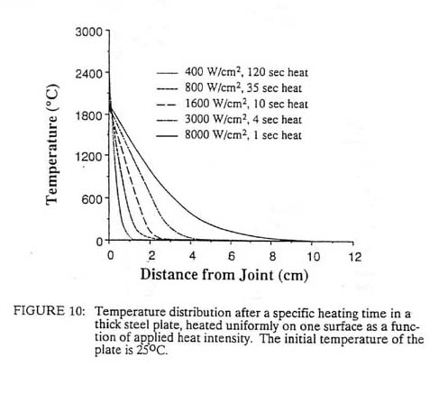
8.1 Heat Source Intensity In fusion welding, intimate interfacial contact is achieved by interposing a liquid of substantially similar composition as the base metal. The surface contamination, if soluble, is dissolved in the liquid and, if insoluble, will float away from the liquid-solid interface. One distinguishing feature of all fusion welding processes is the intensity of the heat source used to melt the liquid. Virtually every concentrated heat source has been applied to welding from time to time; however, many of the characteristics of each heat source are determined by the intensity of the source. For example, if one considers a planar heat source diffusing into a very thick slab, the surface temperature will be a function of both the surface power density and the time. Figure 10 shows how this temperature will vary on steel with power densities from 400 watts/cm2 to 8,000 watts/cm2. At 400 watts/cm2, it takes two minutes to melt the surface. If the 400 watts/cm2 heat source were a point on the flat surface, the heat flow would be divergent and it might not even be possible to melt the steel; the solid metal might be able to conduct away the heat as fast as it is being introduced. Generally, it is found that heat source power densities of approximately 103 watts/cm2 are necessary to melt most metals.
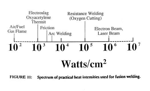
At the other end of the power density spectrum, it is found that heat intensities of 106 or 107 watts/cm2 will cause vaporization of most metals within a few microseconds. Above these power densities, all of the solid interacting with the heat source is vaporized and no fusion welding can occur. Thus it is seen that the heat sources for all fusion welding processes lie between approximately 103 and 106 watts/cm2 on the power density spectrum. This spectrum is shown in Figure 11 with the locations of several common joining processes.
Inspection of Figure 10 shows that the power density is inversely related to the interaction time of the heat source on the material. Since this is a transient heat conduction problem, one can expect the heat to diffuse into the steel to a depth, which increases as the square root of time, i.e. from the Einstein equation
where: x is the distance that the heat diffuses into the solid in
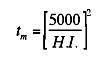
cm For the planar heat source on a steel surface as represented by Figure 10, the time in seconds to produce melting on the surface, tm, is given by:
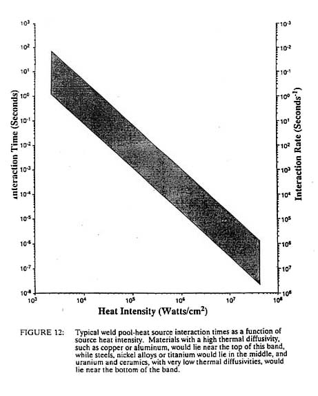
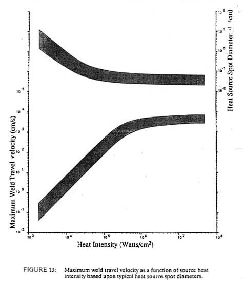
where H.I. is the heat intensity in watts/cm2. If we consider the time to melting to be a characteristic interaction time, tl, we can generate the graph shown in Figure 12. Heat sources of the order of 103 watts/cm2, such as oxyacetylene flames or electroslag welding, require interaction times of 25 seconds with steel while laser and electron beams at 106 watts/cm2 need interaction times on the order of only 25 microseconds. If we divide this interaction time into the heat source diameter, dH, we obtain a maximum travel speed, Vmax, for the welding process, as shown in Figure 13. From this, it is clear why welders begin their training with the oxyacetylene process, as it is inherently slow and does not require rapid response time in order to control the size of the weld puddle. Greater skill is needed to control the more rapid fluctuations in arc processes, while no human can control the pool of the high heat intensity processes such as laser and electron beam. These processes must be automated in order to control them. This need to automate leads to increased capital costs for these high heat intensity processes. We can approximately replace the units of watts/cm2 of a process with the dollar cost of the capital equipment without changing the numbers on the axis. For example, the cost of flame welding equipment is about $1,000 whereas a fully automated laser or electron beam system may cost one million dollars (cf. Figure 11).
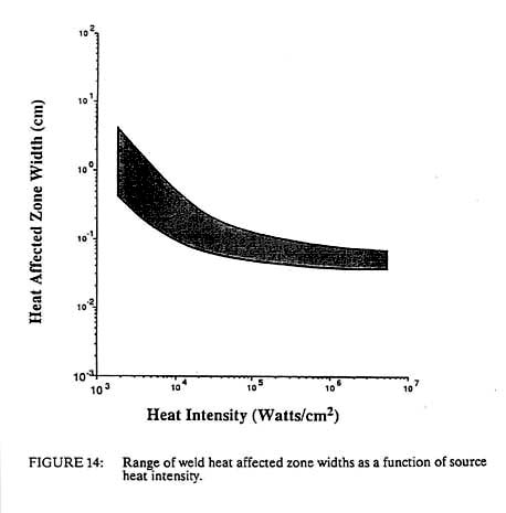
For constant total power, a decrease in the spot size will produce a squared increase in the heat intensity. This is one of the reasons why the spot size decreases with increasing heat intensity as shown in Figure 13. It is easier to make the spot smaller than to increase the power rating of the equipment. In addition, we generally wish to melt only a small volume of material. If the spot size was kept constant and the input power was squared in order to obtain higher densities, the volume of fused metal would increase dramatically with no beneficial effect. However, this decreasing spot size, coupled with a decreased interaction time at higher power densities, compounds the problem of controlling the higher heat intensity process. A shorter interaction time means that the sensors and controllers for automation must operate at higher frequencies. The smaller spot size means that the positioning of the heat source must be even more precise. This positioning accuracy must be on the order of the heat source diameter, dH, while the control frequency must be greater than the travel velocity divided by the diameter of the heat source. For processes operating near the maximum travel velocity, this is the inverse of the process interaction time, tl (see Figure 12). Thus we see that not only must the high heat intensity processes be automated due to an inherently high travel speed, but the fixturing requirements become greater and the control systems and sensors must have ever-higher frequency response. Both of these factors lead to increased costs of high heat intensity processes, which is one reason that laser and electron beam welding, which are very productive, have not found wider use. Another important welding process parameter that is related to the power density of the heat source is the width of the heat affected zone. This is the zone adjacent to the weld metal, which is not melted but is structurally changed due to the heat of welding. Using the Einstein equation we can estimate a heat affected zone width from the process interaction time and the thermal diffusivity of the material. This is shown in Figure 14 with one slight modification. Above about 104 watts/cm2 the heat affected zone width becomes roughly constant. This is due to the fact that the HAZ grows during the heating stage at power densities below 104 watts/cm2 but it grows during the cooling cycle at higher power densities. Thus at low power densities, the HAZ width is controlled by the interaction time, while at high power densities it is independent of the heat source interaction time. In this latter case, the HAZ width grows during the cooling cycle as the heat of fusion is removed from the weld metal. In such a case the HAZ width is proportional to the fusion zone width.
The change of slope in Figure 14 also represents the heat intensity at which the heat utilization efficiency of the process changes. At high heat intensities, nearly all of the heat is used to melt the material and little is wasted in preheating the surroundings. As the heat intensity decreases, this efficiency is reduced. For arc welding, as little as half of the heat generated may enter the plate and only 40 percent of this heat is used to fuse the metal. For oxyacetylene welding it may be 10 percent or less. Finally, the heat intensity also controls the depth to width ratio of the molten pool. This can vary from 0.1 in low heat intensity processes to more than 10 in high beat intensity processes. Thus it is seen that all fusion welding processes can be characterized generally by the heat source intensity. The properties of any new beat source can be estimated readily from the preceding graphs. Nonetheless, it is useful to understand the more common welding heat sources, such as flames, arcs, lasers, electron beam and electrical resistance, in somewhat more detail.
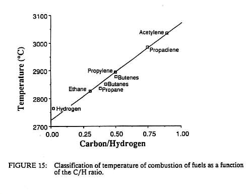
Flames are often categorized in terms of their combustion intensity, CI. This is the product of the heat content of the gas per unit volume, Ch, and the gas velocity, Cv, or CI = Ch * Cv (7) Since Ch has units of J/m3 and Cv has units of cm/s, CI has units of J/cm2/sec or watts/cm2. Thus we see that the combustion intensity is the same as the heat source intensity described above. This intensity is a strong function of the flame temperature, Ch increases directly with temperature, as does Cv, which increases due to the thermal expansion of the gas as it burns; hence, the CI varies roughly as the square of the temperature. This explains why fuel-air flames have little use in fusion welding. The inert nitrogen in the air decreases the flame temperature, by 40 per cent or more, as compared with a fuel-oxygen flame. This in turn will decrease the CI by a factor of three or more. As a result, fuel-air flames rarely produce heat source intensities of greater than 100 watts/cm2. As noted previously, this intensity is generally insufficient to melt the most common metals, such as iron, copper or nickel. On the other band, fuel-oxygen flames produce higher temperatures and hence higher combustion intensities. Values of 1,000 watts/cm2 are not uncommon, and hence flames such as oxyacetylene or oxyhydrogen can be used for welding. Although there are many factors which influence the temperature of a flame such as the fuel-oxygen ratio, the heat of reaction and the speed of the reaction, a very good correlation exists between the maximum flame temperature and the carbon to hydrogen ratio of the fuel, as shown in Figure 15. Acetylene has the highest flame temperature of the common fuels and hence is the most useful for welding; however, there are other fuels, such as methylacetylene-propadiene, which are nearly as hot as acetylene and are much safer to handle.
It should be noted that even small increases in flame temperature could have great influence on the heating value of the gas. For example, in melting steel, 70 per cent of the heat content of an acetylene flame is available above 1,500°C, while less than 30 per cent of the heat of a propylene flame is useful above this temperature. If we compare the experimentally measured CI with a theoretical value representing the total beating value of the flame, the discrepancy is a factor of 10 to 50. This indicates that only 2 to 10 percent of the available beat from the flame flows into the metal. The reason for this poor efficiency is the formation of a gas boundary layer at the flame-metal interface. This boundary layer consists of a much cooler, low velocity gas film, which tends to insulate the metal from the full heat of the flame. Increasing the flame velocity reduces the thickness of the boundary layer and thus increases the rate of heat transfer. There are a number of methods used to increase the velocity. The simplest flame is a diffuse flame in which the fuel and oxygen exit from separate nozzles, diffuse together and burn. This produces a very low velocity, or soft, flame. In a premixed flame, the fuel and oxygen are combined at low temperatures in a chamber, exit as a mixture through a single nozzle and then burn. The interdiffusion is eliminated and the flame propagation velocity is increased. Most welding torches use premixed flames. Finally, in a jet burner, the fuel and oxygen are mixed together and ignited inside a chamber. The constant chamber volume creates a large increase in gas pressure as the temperature rises. The flame exits the chamber through a nozzle at extremely high velocity. The difference in CI between a diffuse flame and a jet burner can be a factor of 10 or more for a given fuel. It is seen that flames are useful for fusion welding, but their heat intensity is marginal. It is necessary to use pure oxygen rather than air as the oxidant in order to achieve the highest flame temperatures. Use of high heat content fuels, such as acetylene, and premixed flames with pure oxygen will provide heat source immensities of 1,000 watts/cm2. This does not permit very rapid production, but the simplicity and portability of the equipment make it very useful for manual welding. One rather interesting variation on flame heating is oxy-fuel cutting. In this process a ring of small premixed flames surrounds a central oxygen jet. The premixed flames heat the surface of the solid, usually steel, to a temperature above the melting point of the surface oxide. When the oxide melts, the central oxygen jet is opened, which blows the molten oxide away. This exposes fresh, hot metal to a pure oxygen jet. The two react and the heat of oxidation causes this newly formed oxide to melt. This is also swept away, causing the process to continue. Oxyflame cutting is often termed "burning" the metal, which is correct terminology as the freshly exposed metal is burned in the pure oxygen. Since the gaseous oxygen is condensed to an oxide, no thick gas boundary layer forms and effective heat intensities of 10,000 to 100,000 watts/cm2 can be achieved. Steel and titanium of more than two-foot thickness can be cut quite rapidly and economically by this process. Unfortunately, stainless steels, aluminum and nickel base alloys cannot be oxygen flame cut without special metal powder additions as their oxides melt at temperatures above the melting point of the metal. Since it is the absence of the gas boundary layer in oxy-fuel cutting, which permits very rapid heat transfer, the presence of inert impurities such as nitrogen in the oxygen should be minimized. In addition, the products of the metal combustion may produce non-reactive gases such as carbon monoxide. For this reason, the flame cutting rate of high carbon steels is much less than that of low carbon steels. 8.3. Electric Arcs An atmospheric pressure plasma arc can be considered an electrically augmented flame. The arc consists of ionized gases, which makes the gas an electrical conductor. Temperatures of 8,000 to 20,000 Kelvin are necessary in order to separate the atoms into electrons and ions. These high temperatures will increase the combustion intensity of the arc flame to 2,000 watts/cm2 but the electron flow can add another 8,000 watts/cm2. Thus the electrons dominate heat transfer in the arc, and the actual plasma temperature is relatively unimportant. The total heat flow to the metal can be separated as follows: Qtotal = Qelectron + Qconduction + Qconvection + Qradiation (8) Of the total power generated in the arc, approximately 50 percent enters the metal, making arcs much more energy-efficient than flames. Of this 50 percent, radiation heat transfer accounts for only 1 percent, convection 2 percent, and conduction 4 percent. The remainder is due to electron flow. This can be further subdivided as:
where I is the welding current in amperes, phi is the work function of the metal in volts (which is equivalent to a heat of condensation as the electrons decay to the energy level of bound electrons in the solid ), Va is the anode voltage drop as the electrons cross the cool gas boundary layer at the metal-plasma interface, and VThomson is a voltage equivalent of the kinetic energy of the electrons in the plasma. The work function is approximately 2.5 times as large as the anode voltage drop, and the anode voltage drop is approximately 2.5 times as large as the Thomson voltage; hence, the anode voltage drop and the work function voltage account for nearly 80 percent of all the heat transferred to the metal by the arc. Just as the electrons carry heat into the anode as they condense into the metal, they carry heat away from the cathode as they exit the metal. Due to this asymmetry of electron flow, one-third to one-half of the total arc energy enters the anode and only one-sixth to one-fourth of the energy enters the cathode. In alternating current arcs, this asymmetric heating is time averaged between the electrode and the workpiece, whereas in direct current welding, which is the largest fraction of all arc welding, the choice of electrode polarity becomes important. If the electrode is inert, as in a gas tungsten arc, we wish to heat the base metal and not the electrode; hence the tungsten electrode is the cathode and the workpiece is the anode. In gas metal arc welding, wherein a wire of similar composition to the base metal is used as the electrode, the electrode is fed into the arc and melts, depositing molten metal into a groove on the base plate. Since the liquid metal for this process is supplied primarily by the electrode, we wish to melt the electrode in order to fill the groove as quickly as possible. For this reason, the electrode is usually the anode and the base plate is the cathode in consumable electrode welding processes. It is often useful to note that the gaseous plasma will usually respond to fluctuations in the process on a time scale of microseconds; the melting drops of the electrode are produced on the order of one every 10 to 100 milliseconds, and the much larger weld pool has a time constant of approximately 100 milliseconds. Thus it is extremely difficult to control fluctuations in the plasma, but much easier to monitor and respond to droplet or weld pool disturbances. An important practical problem, especially in automated welding, is arc ignition and extinction. The extinction process is usually controlled by the welding power supply. Electrical inductance in the circuit usually limits the ability to reduce welding current to zero in times less than 30 milliseconds. Arc ignition can be accomplished by either touch contact of the electrode and the workpiece or by high frequency ripple of the welding voltage. In touch starting the electrode and base metal contact at small local asperities. As current flows and the two are separated, the contact resistance increases and resistive heating can cause vaporization of the local contacts. Theoretical studies show that less than two volts are necessary to vaporize even the most refractory metals. Some of this metal vapor ionizes and the arc is initiated. In high frequency ignition, a voltage ripple of 10 kHz to 100 kHz is added to the welding power supply. When the electrode and base metal are brought together within less than a millimeter, without touching the high frequency voltage induces ionization of the gas between the metals and the arc is ignited. One problem often encountered when welding ferromagnetic alloys such as steel, nickel or cobalt is arc blow. As the welding current flows through the electrode, the arc and the base metal, it often must follow curves or turn comers. Whenever it does so, asymmetric magnetic fields are produced with the stronger fields on the inside curvature. The arc will attempt to avoid these strong magnetic fields and will be pushed to regions of lower magnetic field. In severe cases, the arc can be pushed completely away from the weld joint. Solutions to this problem include use of alternating current if possible, location of more symmetric ground cables on the base plate, use of pulsed current welding or addition of external magnetic fields. Pulsed current welding produces a stiffer arc which is more resistant to arc blow. The reason for this is that a strong plasma gas jet is created from the tip of the welding electrode due to electromagnetic forces. These forces and the velocity of the jet are proportional to the square of the welding current; hence, higher currents produce stronger stiffer jets. Some welding power supplies possess an arc stiffness control which merely increases the ripple of the welding current, thus creating stiffer arcs which are more resistant to arc blow. The plasma arc process is similar in concept to the jet burner of flames. In the plasma arc process, a gas tungsten arc is struck inside a water-cooled copper chamber. The rapidly expanding gases escape at high velocity through an orifice. The welding current can be carried through this plasma flame into the base metal in the transferred plasma arc process. The high jet velocity combined with the arc current will produce 20,000 watts/cm2 on the workpiece, which is double that attainable in a simple gas tungsten arc. If the welding current is only carried between the tungsten electrode and the copper chamber, the process is called non-transferred plasma arc and the maximum heat intensity is approximately 3,000 watts/cm2. The major problem with plasma arc processes is maintenance, as the copper chambers and orifices tend to erode. Nonetheless, the higher heat intensity of plasma arc can be advantageous in welding high thermal conductivity materials such as aluminum or copper.
Laser and electron beams produce the highest heat source intensities used in welding. Although intensities of 109 watts/cm2 are possible, only levels of 106 or 107 watts/cm2 are useful for welding. Above this level, vaporization of the metal is so intense that holes are drilled rather than welds being formed. In these processes, metal vaporization begins in less than 100 microseconds, and the rapidly escaping gases produce a reaction pressure, which pushes the molten metal aside, drilling a cavity in the baseplate. The depth of the hole can be 50 times its width, but for practical welding conditions the depth rarely exceeds ten times the weld width. This deep narrow weld produces less thermal damage to the surrounding metal and reduces distortion as compared with other fusion welding processes. The rapid melting and high travel speeds at these high heat intensities reduce heat loss to the surroundings, with resultant melting efficiencies of 90 per cent or more. Nonetheless, the narrow weld zone and high travel speed make seam tracking difficult. Misalignments or joint separation variations of 0.5 millimeter can produce defective joints; hence preparation and fixturing of parts prior to welding is much more critical than with lower heat intensity processes. The high productivity of these processes is generally only an advantage in very high volume production. The much greater capital equipment costs as compared with arc welding require that the facilities be used on a high duty cycle to achieve economy. This requires a very large volume of similar parts in order to fully utilize even small laser or electron beam machines. It should be recognized that there are important differences in the laser and electron beam processes and hence they cannot always be used interchangeably. Heating in an electron beam involves high energy electrons striking the metal, whereas laser heat is generated by an extremely large number of photons. The electrons have sufficient energy to penetrate a fraction of a millimeter beneath the surface; hence, the greatest heating is subsurface, whereas laser heat is all produced on the surface of a metal. This phenomenon has been used to advantage in electron beam hardening of steel camshaft surfaces. Although this is not fusion welding, as no melting occurs, the high subsurface temperatures produced by electron beam heating produce favorable compressive surface residual stresses. Laser hardened camshafts have tensile surface residual stresses and are prone to development of fatigue cracks in service. The workpiece in electron beam welding must be an electrical conductor, whereas lasers can heat insulators with equal or even greater effectiveness as compared with metals. This is due to the fact that the free electrons in metals tend to reflect the laser light. Indeed, the best electrical conductors, such as silver, copper, gold and aluminum, reflect most laser light and may absorb less than 5 per cent of the incident radiation. For this reason, these metals are more easily welded by electron beam than by laser. The electron beam generally requires a vacuum for consistent results, although atmospheric electron beam machines have seen limited industrial use. The laser can easily be operated in the ambient atmosphere, although helium shielding of the workpiece suppresses the formation of ionized gases above the surface of the metal. Such surface plasmas must be removed by horizontal gas flows or they will interfere with the coupling of the laser beam to the workpiece. Electron beams are easily distorted by magnetic fields. In some cases, thermoelectric currents are produced during electron beam welding of dissimilar materials. If the materials are very thick, the currents will produce magnetic fields, which will distort the beam causing, it to deviate from the weld seam. Lasers on the other hand are not affected by stray magnetic fields. One of the most significant problems with electron beams is that they produce X-rays. Low voltage machines of less than 30 kV produce soft X-rays which are relatively easy to shield, while high voltage machines of 100 kV or greater require elaborate shielding. Laser radiation is relatively easy to shield although the beam is invisible and hence the equipment requires many safety interlocks. The laser radiation is also easily reflected by metal surfaces; hence most work must be performed inside protective enclosures. The current of an electron beam welder is generally limited to one half ampere since the mutual repulsion of the electrons causes the beam to defocus at higher currents. Although the photons of the laser do not interact with each other, the beam itself can contain hot and cold spots due to the wavelike constructive and destructive interference of the light. The beam quality of a laser is determined by the "mode" of these spots. A gaussian mode beam is the best for welding but is not generally available with laser powers above approximately 2kW. In summary, the laser and electron beam processes have many similarities and many differences. They provide some unique advantages such as low distortion and extremely rapid processing; however, they can be very costly except in high volume applications.
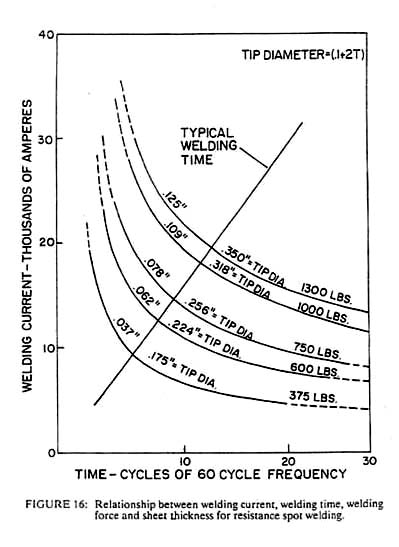
The asperity contact and the surface contamination between two pieces of metal produce a contact resistance at the interface. If a large current is passed across this interface while pressure is applied, sufficient heat can be generated to produce either melting or a solid phase forge weld. In terms of both economy and productivity, resistance welding is the best of all the fusion processes. Heat intensities of 100,000 watts/cm2 can be generated, yielding high production rates using equipment that costs approximately the same as arc welding equipment which is capable of one-tenth as much production. Unfortunately, resistance welding cannot be applied to all sizes of materials in all geometries; however, when it can be applied, it is often the most economical process. It is simple and reliable, but certain weld geometries, such as spot welds in sheet material, are virtually uninspectable and equipment must be maintained or else control of the process will be lost. Other geometries such as butt welds in bar stock or longitudinal seam welds in pipe are readily inspected and hence can produce high reliability and consistent quality at reasonable costs. Electric currents used in resistance welding vary from DC to several hundred thousand Hertz AC, depending on the part geometry and the material being used. Uniform surface properties are necessary for consistent results, since oil, grease, or heavy surface oxides can alter the local heat generation rate significantly. The other primary welding variables are contact pressure, weld current and weld time. Acceptable combinations of these parameters are often defined by a welding lobe as shown in Figure 16. Regions within the lobe define acceptable welds, while longer times, higher currents or lower pressures will produce excessive heating and the opposite variations will produce insufficient heating. Experimental construction of the welding lobe is relatively simple and permits selection of the set of parameters, which lies in the thickest portion of the lobe. It is here that the process is most tolerant of variations in either the process or the material.
Generally, low electrical conductivity metals are easier to weld than higher conductivity metals such as copper or aluminum. In high conductivity materials, it is difficult to design electrodes to introduce enough current to melt the weld interface without also tending to melt the electrode-workpiece interface as well. Indeed, electrode wear is the primary maintenance problem with all forms of resistance welding.
Economical joining requires consideration of the joining process from the initial design stage and selection of material. Not all materials are weldable, but all can be joined in some manner. Low carbon steel is widely used because it is low in cost and is among the most forgiving of all materials when fusion welding is concerned. More exotic metals, composites and ceramics can be very difficult to join; hence, selection of these materials and the design geometry should be reviewed by a welding engineer early in the product planning. While the assumption that any joining problem can be solved is generally true, it is not true that all of the solutions are economical. The costs of joining can exceed 50 percent of the total product cost in many complex assemblies; hence, the joining process must be a specific part of the product design. Once a joining process is selected, accuracy in production of the components and attention to joint cleanliness can pay great dividends. Assembly inaccuracies of a few millimeters in large parts can require recutting, reforming or deposition of excessive weld filler metal, any of which can result in a doubling of the cost of that operation. Dirty joints can result in weld defects such as porosity or cracking, the repair of which can be extremely costly or even impossible. Since joining usually occurs after most of the other work is already in the part, extra attention is warranted in order to avoid costly rework or scrap. The thermal cycle created during fusion welding can produce many undesirable changes in the material. Segregation of alloying elements during solidification can produce hot cracking on cooling. Sometimes redesign of the joint geometry can reduce the stresses during cooling and thus prevent these defects, but in other cases no solution can be found. For this reason, many manufacturers require stringent chemical composition requirements on incoming material. In addition, test welds are often required on sample material or special product geometries. In many cases, welding codes require the production and testing of trial welds before any production begins. Even if a successful weld is produced, subsequent heat treatment can induce cracking. Certain steels are susceptible to reheat cracking during stress relief heat treatments due to metallurgical changes induced by the original weld thermal cycle. Some stainless steels, aluminum alloys or nickel alloys can lose corrosion resistance due to metallurgical changes induced by welding. Fortunately, producers and users of these alloys are generally familiar with problems caused during welding, and numerous sources exist to guide a designer or fabricator in selection of the welding process and procedure. Unless one has extensive experience with both the joining process and the material, it is unwise to assume that no problems will arise. Successful joining is based on extensive industrial experience and cannot yet be categorized into a simple set of rules and formulae. A number of metals, particularly steels and aluminum, are susceptible to defects if hydrogen is present during welding. Any source of hydrogen can be a problem -- moisture, grease, hydroxides or the like. These problems can be alleviated by maintaining strict cleanliness of the joint and welding materials and by preheating above room temperature to vaporize moisture and to allow the hydrogen to diffuse out of the metal before the defects form. Most materials suppliers can provide details of the preheating requirements and procedures necessary for successful welding.
As noted in the introduction, joining technology is an essential component of virtually every manufactured product. The choice of processes and materials can seem endless unless we learn to assess the service requirements of the joint (temperature, strength, hermeticity, corrosion resistance, ease of disassembly, etc.) and to compare these with the capabilities of each process. There often are a number of potential joining processes, from which the most economical process must be chosen. The final answer is rarely found in a single textbook but can generally be assembled by searching a number of sources. As the person who must "put it all together," it is necessary for the welding engineer to interface with virtually every other aspect of the manufacturing process.
Adhesion or Cold Welding of Materials in Space Environments, American Society for Testing and Materials, STP 431, Philadelphia, 1967. I. Skeist, Handbook of Adhesives, 2nd Edition, Van Nostrand, Reinhold, NY, 1977. J. J. Bikerman, The Science of Adhesive Joints, Academic Press, NY, 1961. H. H. Manko, Solders and Soldering, 2nd Edition, McGraw-Hill, NY, 1979. Brazing Manual, American Welding Society, Miami, FL, 1976. P. T. Houldcroft, Welding Process Technology, Cambridge University Press, Cambridge, 1977. Welding Handbook,7th Edition, Volumes 1-5, American Welding Society, Miami, FL.
|
|||||||||
| ▲up ◄home | |||||||||
|
updated 31.03.2017 |
 (1)
(1) 
 (2)
(2)  and if
hi >> hf then 1/hf4
term can be neglected to give:
and if
hi >> hf then 1/hf4
term can be neglected to give: 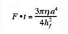 (3)
(3) 
 (4)
(4) 

 (5)
(5)  (6)
(6) 
 (9)
(9)