|
|||||||||||||||||||||||||||||||||||||||||||||||||||||||||||||||
| Designation | ISO | Classification | Filler | Application |
|---|---|---|---|---|
| 1080A | A1998 | NHT | 1080A | Chemical plant |
| 3103 | A1-Mn1 | NHT | 4043A | Buildings, heat exchangers |
| 4043A | A1-Si5 | - | - | Filler wire/rod |
| 5083 | A1-Mg4.5Mn | NHT | 5556A | Ships, rail wagons, bridges |
| 5251 | Al-Mg2 | NHT | 5356 | Road vehicles, marine |
| 5356 | Al-Mg5 | - | - | Filler wire/rod |
| 5556A | AlMg5Mn | - | - | Filler wire/rod |
| 6061 | Al-Mg1SiCn | HT | 4043A/5356 | Structural, pipes |
| 7020 | Al-Zn,4. 5Mg1Mn | HT | 5556A | Structural, transport |
| HT = Heat Treatment NHT = Non heat treatable | ||||
Imperfections in welds
Aluminium and its alloys can be readily welded providing appropriate precautions are taken. The most likely imperfections in fusion welds are:
- porosity
- cracking
- poor weld bead profile
Porosity
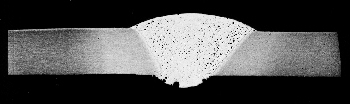
Porosity is often regarded as an inherent feature of MIG welds; typical appearance of finely distributed porosity in a TIG weld is shown in the photograph. The main cause of porosity is absorption of hydrogen in the weld pool which forms discrete pores in the solidifying weld metal. The most common sources of hydrogen are hydrocarbons and moisture from contaminants on the parent material and filler wire surfaces, and water vapour from the shielding gas atmosphere. Even trace levels of hydrogen may exceed the threshold concentration required to nucleate bubbles in the weld pool, aluminium being one of the metals most susceptible to porosity.
To minimise the risk, rigorous cleaning of material surface and filler wire should be carried out. Three cleaning techniques are suitable; mechanical cleaning, solvent degreasing and chemical etch cleaning.
Mechanical cleaning
Wire brushing (stainless steel bristles), scraping or filing can be used to remove surface oxide and contaminants. Degreasing should be carried out before mechanical cleaning.
Solvents
Dipping, spraying or wiping with organic solvents can be used to remove grease, oil, dirt and loose particles.
Chemical etching
A solution of 5% sodium hydroxide can be used for batch cleaning but this should be followed by rinsing in HNO3 and water to remove reaction products on the surface.
In gas shielded welding, air entrainment should be avoided by making sure there is an efficient gas shield and the arc is protected from draughts. Precautions should also be taken to avoid water vapour pickup from gas lines and welding equipment; it is recommended that the welding system is purged for about an hour before use.
Solidification cracks
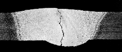
Cracking occurs in aluminium alloys because of high stresses generated across the weld due to the high thermal expansion ( twice that of steel) and the substantial contraction on solidification - typically 5 % more than in equivalent steel welds.
Solidification cracks form in the centre of the weld,, usually extending along the centreline during solidification. Solidification cracks also occur in the weld crater at the end of the welding operation. The main causes of solidification cracks are as follows:
- incorrect filler wire/parent metal combination
- incorrect weld geometry
- welding under high restraint conditions
The cracking risk can be reduced by using a non-matching, crack-resistant filler (usually from the 4xxx and 5xxx series alloys). The disadvantage is that the resulting weld metal may have a lower strength than the parent metal and not respond to a subsequent heat treatment. The weld bead must be thick enough to withstand contraction stresses. Also, the degree of restraint on the weld can be minimised by using correct edge preparation, accurate joint set up and correct weld sequence.
Liquation cracking
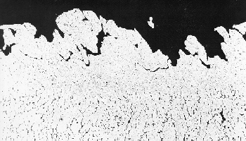
Liquation cracking occurs in the HAZ, when low melting point films are formed at the grain boundaries. These cannot withstand the contraction stresses generated when the weld metal solidifies and cools. Heat treatable alloys, 6xxx, 7xxx and 8xxx series alloys, are more susceptible to this type of cracking.
The risk can be reduced by using a filler metal with a lower melting temperature than the parent metal, for example the 6xxx series alloys are welded with a 4xxx filler metal. However, 4xxx filler metal should not be used to weld high magnesium alloys (such as 5083) as excessive magnesium-silicide may form at the fusion boundary decreasing ductility and increasing crack sensitivity.
Poor weld bead profile
Incorrect welding parameter settings or poor welder technique can introduce weld profile imperfections such as lack of fusion, lack of penetration and undercut. The high thermal conductivity of aluminium and the rapidly solidifying weld pool make these alloys particularly susceptible to profile imperfections.
| ◄home |
▲ |
Copyright © 1999, TWI Ltd |