|
 |
Fig.1.
|
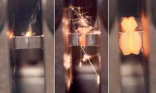 |
Fig.2.
|
The two components are brought into perfect alignment towards the end of the weld cycle, and the welding force is maintained or increased to consolidate the joint.
Current status
A British patent issued in 1969 described a linear reciprocating mechanism for welding mild steel, although no further information was published. In the early 1980s, TWI demonstrated the viability of the LFW technique for metals using modified equipment. The design and build of a prototype electro-mechanical machine with a linear reciprocating mechanism followed in the mid 1980s. Two similar machines are now located at an aircraft engine manufacturer in Europe. Several other machines of alternative designs are operating in the USA and Europe.
Although available for 10 years, the LFW process has only found industrial application in aircraft engine manufacture, in part due to the high cost of the welding machines. It has proved to be an ideal process for joining turbine blades to discs where the high value-added cost of the components justifies the cost of a LFW machine. This approach is more cost-effective than machining blade/disc (blisks) assemblies from solid billets.
LFW has been used successfully to join a range of materials including steel, intermetallic materials, aluminium, nickel and titanium alloys with the greatest emphasis on aircraft engine alloys. The process has also been demonstrated as an effectice way for joining copper to aluminium for electrical conductors.
Current issues
In recent years, LFW research programmes have addressed the following
topics:
|
|
|
|
|
However, to increase greatly the application of LFW in industries such as automotive and power generation, the cost of linear friction welding machines must be drastically reduced. An EU funded study has recently been completed to build a low cost LFW machine. This increases TWI's capability to two machines.
Benefits
The benefits of linear friction welding are:
|
|
|
|
Risks
Linear friction welding is regarded as unproven technology for applications outside the aircraft engine industry. Hence, there is a degree of risk associated with the high level of investment in a LFW machine for non-aircraft engine application. However, TWI's experience of welding many materials can minimise this risk, and TWI's machines are available for R&D and prototype development.
| ◄back |
Copyright 2001, TWI Ltd |
| ▼home |