Stephan Kallee and Dave Nicholas
|
||||||||||||||||
|
|
||||||||||||||||
Friction Stir Welding - Process advantagesThe process advantages result from the fact that the FSW process (as all friction welding of metals) takes place in the solid phase below the melting point of the materials to be joined. The benefits therefore include the ability to join materials which are difficult to fusion weld, for example 2000 and 7000 aluminium alloys. Other advantages are as follows:
Friction stir welding can use existing and readily available machine tool technology. The process is also suitable for automation and adaptable for robot use. Its main advantages are:
The limitations of the FSW process are being reduced by intensive research and development. However, the main limitations of the FSW process are at present:
|
||||||||||||||||
|
|
||||||||||||||||
Friction Stir Welding - Materials and thicknessesFriction stir welding can be used for joining many types of materials and material combinations, if tool materials and designs can be found which operate at the forging temperature of the workpieces. Up to the present day, TWI has concentrated most of its efforts to optimising the process for the joining of aluminium and its alloys. A major Group Sponsored Project undertaken for TWI's Industrial Members demonstrated that the following aluminium alloys could be successfully welded to yield reproducible, high integrity welds within defined parametric tolerances.
 This work primarily investigated welding of wrought and extruded alloys.
However, subsequent studies have shown that cast to cast, and cast to
extruded (wrought) combinations, in similar and dissimilar aluminium
alloys are equally possible.
This work primarily investigated welding of wrought and extruded alloys.
However, subsequent studies have shown that cast to cast, and cast to
extruded (wrought) combinations, in similar and dissimilar aluminium
alloys are equally possible.
Continuing development of the FSW tool, its design and materials have allowed preliminary welds to be successfully produced in:
|
||||||||||||||||
|
|
||||||||||||||||
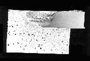
Friction Stir Welding - Superior weld qualityThe repeatable quality of the solid-phase welds can improve existing products and lead to a number of new product designs previously not possible. Welds with the highest quality can be achieved by friction stir welding. The crushing, stirring and forging action of the FSW tool produces a weld with a finer microstructure than the parent material. The weld metal strength can be, in the as welded condition, in excess of that in the thermo-mechanically affected zone. In the case of annealed materials in the O condition, tensile tests usually fail in the parent material well away from the weld and heat affected zone, as the following results show:Tensile test data for friction stir welds in 6mm thick aluminium alloy 5083 in the O condition (average of three samples taken over 400mm weld length)
The weld properties of fully hardened (cold worked or heat treated) alloys can be further improved by controlling the thermal cycle, in particular by reducing the annealing and overageing effects in the thermo-mechanically affected zone, where the lowest hardness and strength are found after welding. For optimum properties, it would seem that, for the latter, a heat treatment after welding is the best choice, although it is recognised that this will not be a practical solution for many applications. Further studies are necessary and are currently being conducted to explain the complex microstructural aspects of friction stir welds and their corrosion properties. Fatigue tests on friction stir welds made from 6mm thick 5083-O and 2014-T6 were conducted in tension. The preliminary results are quite exceptional in that they show little scatter and are far better than those of fusion welding processes such as GTA and MIG. The fatigue performance of friction stir welds in alloy 5083-O is comparable to that of the parent material when tested using a stress ratio of 0:1. Despite the fact that the fatigue tested friction stir welds were single pass from one side, the results have substantially exceeded BS 8118 class 35 and the European design recommendation ECCS B3 for fusion welded joints. Microstructure ClassificationThe first attempt at classifying microstructures was made by P L Threadgill (Bulletin, March 1997). This work was based solely on information available from aluminium alloys. However, it has become evident from work on other materials that the behaviour of aluminium alloys is not typical of most metallic materials, and therefore the scheme cannot be broadened to encompass all materials. It is therefore proposed that the following revised scheme is used. This has been developed at TWI, but has been discussed with a number of appropriate people in industry and academia, and has also been provisionally accepted by the Friction Stir Welding Licensees Association. The system divides the weld zone into distinct regions as follows: A. Unaffected material B. Heat affected zone (HAZ) C. Thermo-mechanically affected zone (TMAZ) D. Weld nugget (Part of thermo-mechanically affected zone) Unaffected material or parent metal: This is material remote from the weld, which has not been deformed, and which although it may have experienced a thermal cycle from the weld is not affected by the heat in terms of microstructure or mechanical properties. Heat affected zone (HAZ): In this region, which clearly will lie closer to the weld centre, the material has experienced a thermal cycle which has modified the microstructure and/or the mechanical properties. However, there is no plastic deformation occurring in this area. In the previous system, this was referred to as the "thermally affected zone". The term heat affected zone is now preferred, as this is a direct parallel with the heat affected zone in other thermal processes, and there is little justification for a separate name. Thermo-mechanically affected zone (TMAZ): In this region, the material has been plastically deformed by the friction stir welding tool, and the heat from the process will also have exerted some influence on the material. In the case of aluminium, it is possible to get significant plastic strain without recrystallisation in this region, and there is generally a distinct boundary between the recrystallised zone and the deformed zones of the TMAZ. In the earlier classification, these two sub-zones were treated as distinct microstructural regions. However, subsequent work on other materials has shown that aluminium behaves in a different manner to most other materials, in that it can be extensively deformed at high temperature without recrystallisation. In other materials, the distinct recrystallised region (the nugget) is absent, and the whole of the TMAZ appears to be recrystallised. This is certainly true of materials which have no thermally induced phase transformation which will in itself induce recrystallisation without strain, for example pure titanium, b titanium alloys, austenitic stainless steels and copper. In materials such as ferritic steels and a-b titanium alloys (e.g.Ti-6Al-4V), understanding the microstructure is made more difficult by the thermally induced phase transformation, and this can also make the HAZ/TMAZ boundary difficult to identify precisely. Weld Nugget: The recrystallised area in the TMAZ in aluminium alloys has traditionally been called the nugget. Although this term is descriptive, it is not very scientific. However, its use has become widespread, and as there is no word which is equally simple with greater scientific merit, this term has been adopted. A schematic diagram is shown in the above Figure which clearly identifies the various regions. It has been suggested that the area immediately below the tool shoulder (which is clearly part of the TMAZ) should be given a separate category, as the grain structure is often different here. The microstructure here is determined by rubbing by the rear face of the shoulder, and the material may have cooled below its maximum. It is suggested that this area is treated as a separate sub-zone of the TMAZ. |
||||||||||||||||
|
|
||||||||||||||||
Friction Stir Welding - Joint geometries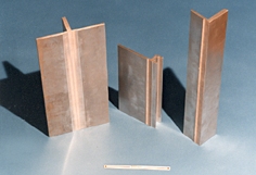 The process has been used for the manufacture of butt welds, overlap
welds, T-sections, fillet, and corner welds. For each of these joint
geometries specific tool designs are required which are being further
developed and optimised. Longitudinal butt welds and circumferential lap
welds of Al alloy fuel tanks for space flights have been friction stir
welded and successfully tested.
The process has been used for the manufacture of butt welds, overlap
welds, T-sections, fillet, and corner welds. For each of these joint
geometries specific tool designs are required which are being further
developed and optimised. Longitudinal butt welds and circumferential lap
welds of Al alloy fuel tanks for space flights have been friction stir
welded and successfully tested.
The FSW process can also cope with circumferential, annular, non-linear, and three dimensional welds. Since gravity has no influence on the solid-phase welding process, it can be used in all positions, viz:
|
||||||||||||||||
|
|
||||||||||||||||
Friction Stir Welding - ApplicationsShipbuilding and marine industriesThe shipbuilding and marine industries are two of the first industry sectors which have adopted the process for commercial applications. The process is suitable for the following applications:
Aerospace industryAt present the aerospace industry is welding prototype parts by friction stir welding. Opportunities exist to weld skins to spars, ribs, and stringers for use in military and civilian aircraft. This offers significant advantages compared to riveting and machining from solid, such as reduced manufacturing costs and weight savings. Longitudinal butt welds and circumferential lap welds of Al alloy fuel tanks for space vehicles have been friction stir welded and successfully tested. The process could also be used to increase the size of commercially available sheets by welding them before forming. The friction stir welding process can therefore be considered for:
Railway industryThe commercial production of high speed trains made from aluminium extrusions which may be joined by friction stir welding has been published. Applications include:
Land transportationThe friction stir welding process is currently being experimentally assessed by several automotive companies and suppliers to this industrial sector for its commercial application. A joint EWI/TWI Group Sponsored Project is investigating representative joint designs for automotive lightweight structures. Potential applications are:
Construction industryThe use of portable FSW equipment is possible for:
Electrical industryThe electrical industry shows increasing interest in the application of friction stir welding for:
Other industry sectorsFriction stir welding can also be considered for:
|
||||||||||||||||
|
|
||||||||||||||||
Friction Stir Welding - EquipmentFriction stir welding machines are commercially available from several machine manufacturers and include installations for welding up to 16 m lengths. The following companies are licensed by TWI to supply FSW equipment:Friction stir welding equipment manufacturers(as at 18 February 2003)
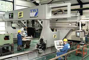 TWI installed an ESAB SuperStirTM
machine in its friction welding laboratory, which is being used in the
EUREKA EuroStir® Project
www.eurostir.co.uk
and for confidential studies. The machine has a vacuum clamping table
and can be used for non-linear joint lines.
TWI installed an ESAB SuperStirTM
machine in its friction welding laboratory, which is being used in the
EUREKA EuroStir® Project
www.eurostir.co.uk
and for confidential studies. The machine has a vacuum clamping table
and can be used for non-linear joint lines.
With ever increasing interest in the process from many industrial
sectors, there is the need for continual process development and
fabrication of prototype assemblies. Consequently, to meet these needs
dedicated equipment has to be developed. A range of modified machine
tools now exists at TWI which are briefly reviewed below: 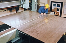 A laboratory machine was built in October 1996 to accommodate large
sheets and to weld prototype structures. The modular construction of
FW22 enables it to be easily enlarged for specimens with even larger
dimensions.
A laboratory machine was built in October 1996 to accommodate large
sheets and to weld prototype structures. The modular construction of
FW22 enables it to be easily enlarged for specimens with even larger
dimensions.
Moving gantry machine FW21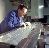 The purpose built friction stir welding machine FW21 was built in 1995.
This machine uses a moving gantry, with which straight welds up to 2m
long can be made. It was used to prove that welding conditions can be
achieved which guarantee constant weld quality over the full length of
long welds.
The purpose built friction stir welding machine FW21 was built in 1995.
This machine uses a moving gantry, with which straight welds up to 2m
long can be made. It was used to prove that welding conditions can be
achieved which guarantee constant weld quality over the full length of
long welds.
Heavy duty Friction Stir Welding machines FW18 and FW14Two existing machines within TWI's Friction and Forge Welding Group have been modified exclusively to weld thick sections by FSW. The following thickness range has been experimentally investigated but the machine are not yet at their limits.
High rotation speed machine FW20For welding thin aluminium sheets TWI equipped one of its existing machines with an air cooled high speed head which allows rotation speeds of up to 15,000rev/min.
Friction Stir Welding demonstrator FW16TWI's small transportable machine produces annular welds with hexagonal aluminium alloy discs. It has been exhibited on fairs in USA, Sweden, Germany, and the United Kingdom in recent years. It is an eye catcher which enables visitors to produce their first friction stir weld themselves. It can be operated with 110V or 220V-240V and has been used by TWI and its member companies to demonstrate the process.Other machinesPortable CRC machineTWI commissioned a prototype machine which was designed and manufactured by their CRC partners at the Department for Mechanical Engineering of the University of Adelaide, Australia. This machine can be carried and aligned by two operators without the use of a crane or other lifting device. It has been used to weld curved sheets under site conditions in a shipyard.Commercially available FSW machines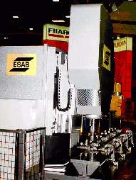 Purpose built friction stir welding machines have been designed,
manufactured, and commissioned. One of them, which is installed at
Marine Aluminium Aanensen, Norway, is capable of making 16m long welds.
It was built by ESAB in Laxå, Sweden and is used for the mass
production of panels which are made by joining extruded profiles. The
machine and the welding procedure have been approved by Det Norske
Veritas and Germanischer Lloyd. Several shorter machines, some of them
with CNC systems of up to 5 axes, have been built for experiments and
for the production of prototype parts. ESAB demonstrated FSW with a
welding speed of 750mm/min in 5mm thick aluminium (6000 series) at the
14th International Welding Fair in Essen. Even friction stir welds with
very rigid robots were successful and demonstrated the possibility of
non-linear welds.
Purpose built friction stir welding machines have been designed,
manufactured, and commissioned. One of them, which is installed at
Marine Aluminium Aanensen, Norway, is capable of making 16m long welds.
It was built by ESAB in Laxå, Sweden and is used for the mass
production of panels which are made by joining extruded profiles. The
machine and the welding procedure have been approved by Det Norske
Veritas and Germanischer Lloyd. Several shorter machines, some of them
with CNC systems of up to 5 axes, have been built for experiments and
for the production of prototype parts. ESAB demonstrated FSW with a
welding speed of 750mm/min in 5mm thick aluminium (6000 series) at the
14th International Welding Fair in Essen. Even friction stir welds with
very rigid robots were successful and demonstrated the possibility of
non-linear welds.
|
||||||||||||||||
|
|
||||||||||||||||
|
 In friction stir welding (FSW) a cylindrical, shouldered tool with a
profiled probe is rotated and slowly plunged into the joint line between
two pieces of sheet or plate material, which are butted together. The
parts have to be clamped onto a backing bar in a manner that prevents the
abutting joint faces from being forced apart. Frictional heat is generated
between the wear resistant welding tool and the material of the
workpieces. This heat causes the latter to soften without reaching the
melting point and allows traversing of the tool along the weld line. The
plasticised material is transferred from the leading edge of the tool to
the trailing edge of the tool probe and is forged by the intimate contact
of the tool shoulder and the pin profile. It leaves a solid phase bond
between the two pieces. The process can be regarded as a solid phase
keyhole welding technique since a hole to accommodate the probe is
generated, then filled during the welding sequence.
In friction stir welding (FSW) a cylindrical, shouldered tool with a
profiled probe is rotated and slowly plunged into the joint line between
two pieces of sheet or plate material, which are butted together. The
parts have to be clamped onto a backing bar in a manner that prevents the
abutting joint faces from being forced apart. Frictional heat is generated
between the wear resistant welding tool and the material of the
workpieces. This heat causes the latter to soften without reaching the
melting point and allows traversing of the tool along the weld line. The
plasticised material is transferred from the leading edge of the tool to
the trailing edge of the tool probe and is forged by the intimate contact
of the tool shoulder and the pin profile. It leaves a solid phase bond
between the two pieces. The process can be regarded as a solid phase
keyhole welding technique since a hole to accommodate the probe is
generated, then filled during the welding sequence.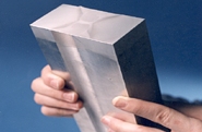 Single pass butt joints with aluminium alloys have been made in
thicknesses ranging from 1.2mm to 50mm without the need for a weld
preparation. Thicknesses of up to 100mm can be welded using two passes,
one from each side, with 6082 aluminium alloy. Parameters for butt
welding of most aluminium alloys have been optimised in a thickness
range from 1.6mm to 10mm. Special lap joining tools have also been
developed for aluminium with thicknesses of 1.2mm to 6.4mm.
Single pass butt joints with aluminium alloys have been made in
thicknesses ranging from 1.2mm to 50mm without the need for a weld
preparation. Thicknesses of up to 100mm can be welded using two passes,
one from each side, with 6082 aluminium alloy. Parameters for butt
welding of most aluminium alloys have been optimised in a thickness
range from 1.6mm to 10mm. Special lap joining tools have also been
developed for aluminium with thicknesses of 1.2mm to 6.4mm.