|
 |
Fig.1. Schematic representation of a flash welding machine |
When welding larger sections, the parts may be preheated to promote easier flashing. This is done by advancing and retracting the components to make repeated short circuit contacts under pressure.
The flashing sequence must be accurately controlled and the forge applied with sufficient force and speed for best results. The forward motion of the components is normally accelerated as flashing progresses. The flashing speed should be as fast as practicable for a given flashing voltage, whilst avoiding premature butting or 'freezing' of the parts. This ensures that the flashing action is continuous and not so coarse that deep craters are blown in the surfaces to be joined, as this increases the risk of interfacial defects. These take the form of a film or planar distribution of oxide inclusions known as 'flat spots'. Insufficient forge may also cause flat spots or result in retained melted or overheated material at the interface.
Current status
Equipment is available to join a range of material sizes and types, from thin steel strip around 0.8mm to 150mm diameter mooring chain. Nickel alloy and titanium aero-engine rings, see Fig.2, and aluminium alloy sections are also flash welded.
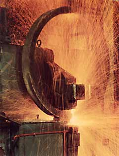 |
Fig.2. Flash welding of a 1200mm diameter aero-engine ring |
Important issues
Concerns with flash welding are usually associated with weld quality.
- Careful setting up and control of the welding sequence, particularly flashing and upset, are required to ensure freedom from weld discontinuities.
- Servo controlled machines, which may also have sequence monitoring, provide adaptive control of the flashing stage.
- Flash welds in steels have a low impact toughness performance and require post-weld heat treatment for applications where impact toughness is specified.
- Certain weld interface flaws, such as flat spots, are not readily detected by non-destructive testing techniques.
Benefits
Flash welding is ideally suited to producing butt welds in large or complex sections. Weld time is relatively short, from a few seconds for the thinnest sections to a few minutes for the largest.
Risks
The main hazards are: (i) the risk of crushing fingers or hands; and (ii) burns or eye damage from splash metal.
| ◄back |
Copyright 2001, TWI Ltd |
| ▼home |